Saintcon 2022 - Minibadge creation
SaintCon 2022 was a great conference. The UtahSAINT organization works tirelessly year after year to plan and host the conference, and they never disappoint. SaintCon 2022 was my fourth year attending the conference.
Over the past six or seven years, the main conference badges have been designed with minibadge slots. Generally 8 of them. Minibadges are .8in x .8in electronic pcbs that anyone can create to either trade, sell, or give to others for free. They seat and interface directly with the main conference badges. Other custom PCBs can be created to seat minibadges. Here’s a 10x10 display panel filled with minibadges, made by the community:

In 2022, I embarked on my first venture into designing and fabricating minibadges. While not an expert in electrical engineering, I had some experience tinkering with simple circuits using breadboards, Arduino, and various electrical components. Additionally, I had previously used a reflow oven that I purchased for soldering SMD components, such as U2F USB boards. I soldered and programmed these boards at a conference a few years earlier when I volunteered as staff. Drawing from these experiences, I felt confident in taking on the challenge of creating minibadges and anticipated learning new skills along the way. However, using software like KiCad to design circuits with custom solder mask graphics on PCBs was uncharted territory for me.
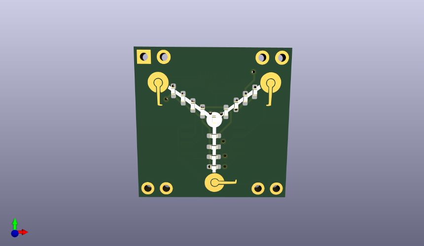
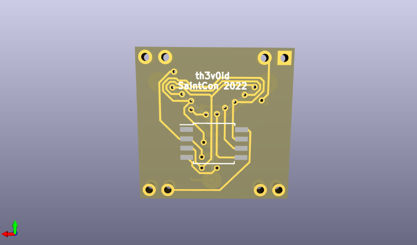
The first minibadge I designed was a Flux Capacitor. It features 13 SMD LEDs (size: 0603) on the front side, controlled by an ATTiny85 SMD microcontroller on the back side. Additionally, there’s a Flux Capacitor graphic on the front. Below are pictures of the minibadge as viewed in KiCad’s PCBViewer:
Here is a schematic illustrating the LED connections to the ATTiny85 microcontroller. The design features four sets of three LEDs and a single LED positioned at the center of the flux capacitor. These LED groups are wired together in parallel, enabling them to light up simultaneously with only one pin connection per group. This setup allows for driving 13 LEDs using just 5 pins on the microcontroller.
The flux capacitor consists of three arms forming a Y shape. Each set of three LEDs comprises one LED on each arm, aligned in the same position. For instance, the three innermost LEDs on the arms are interconnected, continuing in this manner up to the outermost LEDs. This configuration enables the creation of the flux capacitor strobing animation.
One significant issue with this circuit is the excessive brightness of the LEDs due to the absence of resistors to regulate the voltage. The intense brightness makes the minibadge uncomfortable to look at, and it has been a primary complaint about the minibadges. Version 2 will incorporate resistors to address this concern.

The general process for creating a pcb is - create schematic, annotate components, generate netlist, PCB layout (), design rule check (DRC), generating gerber files, reviewing / exporting, and then finally, manufacturing.
Assembling the badge is a straightforward process. It involves applying solder paste to the pads, placing the components on the solder paste, and then putting it in then reflow oven to solder.

The reflow oven utilizes electromagnetic radiation emitted from a ceramic heating element. It gradually raises the temperature to a specific point where the solder paste liquefies, bonding the components to the board. Once the solder has melted, the oven reduces the temperature, completing the soldering process.

The last step is flashing the ATTiny85 with code that drives the LEDs. To do so, I used a bus pirate and a SOP8 IC Flash Clip. The code is nothing special - just a couple of loops with variable delays to create a strobing flux capacitor animation.
#include <avr/io.h>
#include "Arduino.h"

const int NUM_LEDS = 5;

const int leds[NUM_LEDS] = {PB4, PB3, PB2, PB1, PB0};


void setup() {
    for (int i = 0; i < NUM_LEDS; i++) {
        pinMode(leds[i], OUTPUT);
    }
}

void loop() {
    for (int i = 0; i < 30; i++) {
        int d = (i <= 25 ? 40 - i : 20);
        for (int i = 0; i < NUM_LEDS; i++) {
            PORTB |= (1 << leds[i]); // led on
            delay(d);
            PORTB &= ~(1 << leds[i]); // led off
        }
        delay(100);
    }
    delay(3000);
}

